A motorised gate brings benefits
by Jude Woodside
When Karl Bishop had finished fixing and painting the fence on his newly acquired house he knew he needed to finish it with a gate.
A gate would allow the dog to roam safely and it would add an element of security. He wanted an automatic gate. It would mean no more getting out in the wet to open and close it. With the benefit that he worked for an engineering workshop, he knew that making the gate wasn’t likely to be a problem.
He didn’t want an elaborate gate, rather one in keeping with his house that would tone in with the wooden fence. He was able to secure all the parts he required locally including the drive motor and the wheels for the gate. The gate would be galvanised and powder-coated. As designed, it was made from 2.5 mm walled, 40 mm x 40 mm square section steel. The base would be 75 mm x 40 mm with 13 mm tube steel droppers. There are two options for installing the wheels in the gate:
• proud of the frame; or
• enclosed.
Karl opted to use the enclosed method as it kept the gate closer to the ground and made for a neater profile. Karl used the inset method where the wheels are largely enclosed in the bottom member of the gate. “In hindsight, I’d use 150 mm x 50 mm wide on the bottom because although it worked out well, placing the wheels on the bottom was a close fit with no margin for error,” says Karl. There are two kinds of wheels; V-shaped wheels and U-shaped.
The U-shaped wheels are more forgiving if there are any loose stones that might get lodged in the wheel. The first wheel is usually placed about 1 metre from the front end and the second near midway or just past midway.
The gate being built
Galvanizing
While the build was straightforward there was some trouble with the finishing.
The gate wouldn’t fit the vats of the galvanizing company located directly across the road from his workplace. At their suggestion, another nearby outfit to have the gate hot-dip galvanized. The good news was the gate would fit easily into their hot zinc baths. The bad news was that two air holes had to be drilled in every dropper and in the frame.
When pieces are dipped into molten zinc at 420 ˚C, unless there is somewhere for the superheated air in the tubing to escape, they can explode which is particularly dangerous for the people operating the dip. “ I would use solid rod if I did it again. The additional weight isn’t that much of an issue,” admits Karl.
Karl test fi tting the wheels
Mushroom head slit drive pin
Powdercoating
It’s important to remember to ask for the piece to be allowed to air-dry after dipping, too, and not be water-quenched as is commonly done, especially if you intend to powdercoat the finished article.
The powder-coating can absorb some water that will bubble out later in the powdercoat oven. Once the gate was cleaned up and the holes filled it was taken to Powdercoating Specialist Ltd in Auckland.
Site
Meanwhile, Karl had been preparing the site.
Conveniently, his house already had power to the fence through a now-disused external light attached to a standard. Normally it is advisable to place two posts on either side of the opening of at least 100 mm x 100 mm. They hold the guide brackets that grip the top of the gate and the gate-catcher that retains it in the closed position.
Karl already had these in place with the established fence. The first thing to prepare is the concrete pad for the track to run on. This is no more than a strip 250 mm by 250 mm deep depending on your ground conditions. But it must be twice the length of the gate. In Karl’s case, the existing driveway was level and good enough that he only needed to concrete the length of the gate.
“Nailing” the track in place
Leveling and accuracy
It is critical to get the track positioned correctly.
Run a string line for accuracy and check for level. The track is supplied in several lengths and is bolted to the concrete. In this case, Karl used mushroom-headed split nails that deform in the hole when struck. Any kind of concrete anchor could be used and there are several types that use a nail as a deforming agent. The mushroom head ensures there are no sharp bolt or nut edges to shred toes or tyres on the track.
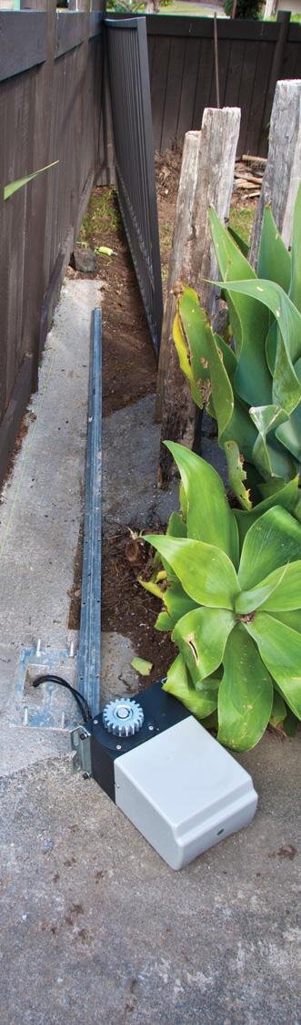
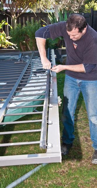
With the track in place, you can test the gate on it to ensure that it runs without hindrance. The drive gear rack should be set so the top of the pinion is 1-2 mm short of the top of the rack. This is easily achieved by placing 1 mm or 1.2 mm washers under the motor mounts while you set the height of the rack.
Use the manual override to allow the gate to run freely on the pinion. Ensure the track is level by running the gate manually over the pinion, synching the bolts as required. Once the rack is installed, remove the gate and the washers from the motor mount. The rack should then have the required clearance.
With the drive rack in place on the gate, the motor is installed and the bolts holding it tightened in place. Now is the time to install the guide rollers and the gate stops. At the same time, Karl’s electrician was installing the controls for the unit, including the 10 amp isolation switch using the pre-existing power cable. This switch means the gate can be switched off in the event of an emergency.
Switches
With the gate in place and running freely, it was only necessary to add the limit switches for the motor. These are magnets that are detected by a Hall-effect sensor in the motor housing and serve to tell the motor when to stop. One is set up with the gate closed that indicates the point where the motor stops and the other with the gate fully open when it must stop the motor.
The sensors are set up on the gate attached to the bottom rail at differing heights in order to contact the two separate sensors. The instructions with your unit will explain this in more detail.
Fitting the top bracket
Fitting the open limit switch
Safety
At this point, it is useful to connect and test any safety measures.
The motor drives should incorporate an automatic cut-off which operates if the gate encounters any obstruction.
The level of this obstructive force can be set so that minor obstructions are ignored and the gate is not shut down by a gust of wind, for example. But if it comes into contact with a child, pet, or your car door it will quickly shut down.
There are many ways of operating the gate other than the remote key. You can install a keypad at the gatepost for visitors and pedestrians. Depending on your model, it’s even possible to operate the gate via your smartphone. Most of these are optional accessories that can be purchased from your motor drive supplier. It is important that the 240V connection is carried out by a qualifi ed electrician and you will also need one to run power from the house to the gate. You can buy units that operate off 24 volt DC although they may be limited in the size and the weight of the gate they can operate but they are ideal for off-grid locations.
Magnetic limit switch
The isolation switch