Homemade bench holdfast

A bench needs clamps, a second pair of hands to hold the work still and stable. Traditionally, woodworkers have used a holdfast and the most popular of these was the Record holdfast, now sadly out of production.


The original Record holdfast


The swivel foot. Note the fingers

Make a handy and useful addition to your workbench

A bench needs clamps, a second pair of hands to hold the work still and stable. Traditionally, woodworkers have used a holdfast and the most popular of these was the Record holdfast, now sadly out of production.
The advantage of the holdfast is its ability to be positioned in various spots on a bench to hold work. The principle is simple enough. The threaded rod is placed at a slight angle to the tube such that when pressure is applied, the rod jams itself in a slightly oversize hole through the bench.
The construction is simple. It uses ¾ inch galvanised water pipe about 350mm long, a bar of 25mm x 6mm flat mild steel bar, about 250mm of threaded rod (we used 12 x 1.75mm pitch rod) and a tapped ferrule from mild steel rod. You will also need a swivelling foot and some means of fixing it, and finally an adjustment knob of some kind to tighten the rod.

Support Tube

Cut the ¾” water pipe to a length of 350 mm, deburr both ends, and mark the slot for the positioning arm to be cut. Drill a series of holes right through the pipe as close together as possible to allow the flat bar to slide freely through. File the slot smooth.


Positioning Arm

Cut the arm to length, debur the ends and clean the end to be welded.

Welded Ferrule

Cut from 22mm dia (not critical) to match the width of the positioning arm. Chamfer the edges at both ends. Centre drill then pilot drill using approximately a 5mm twist drill and finish drill to 10.5mm dia. To determine the tapping drill size for ISO metric threads, take the full outside diameter and subtract the pitch – for our tap drill size above it is 12mm – 1.75 = 10.25mm. I have specified a 10.5mm drill to give a 97.6 percent thread engagement which makes it easier to use a 12mm hand tap.
Cut the threaded rod to length (250 mm) and turn one end to 10mm dia and tap it to 10mm. Using a 6mm drill, drill the other end to a depth of 22mm to accommodate

Swivel Foot

This consists of a 6mm x 28mm rod welded to a ball bearing of about 11mm dia. The foot is made from a slug of 30mm dia mild steel rod, turned to have a boss of 17mm dia x 12mm long. Drill a hole into the boss 1mm greater than the dia of the ball bearing. Cuts made across the boss to about 5mm depth form “fingers” to grasp the ball end of the rod assembly. The fingers are swaged over to capture the ball without restricting its movement.
With the ball bearing rod inserted into the end of the threaded rod, drill a 3mm hole through both the threaded rod and the ball bearing rod, insert a small nail, and swage it in with a centre punch. The threaded adjustment rod is than fed through the ferrule and the adjustment knob screwed on.

Share:

More Posts

Race cars made in NZ

Craig Greenwood is one of the best examples of someone who turned his passion into a business. He is also one of New Zealand’s most prolific racing car builders.
Craig got into motor racing in the early 1990s, progressing from competitive cart racing to Formula Vee (now Formula First). The class is based on a 1200 cc VW motor and uses a collection of stock parts to form a competitive car from the engine, transmission, front suspension, brakes and wheels built into a space frame.
The body is fibreglass or carbon fibre. It’s a racing class that allows an enthusiast to build and maintain his own car. Craig bought his first car but soon decided to build his own, working nights and weekends in a cramped single garage with little more than an oxy-acetylene welder, a hacksaw and a hand-held drill.
“I wasn’t all that successful at first. Of 18 starts I made, I only finished four,” says Craig.
“I realised that just knowing how to weld a chassis wasn’t enough, so I started to read about designing and building race cars.”

The Shed magazine August/September 2025 issue 122 on sale now

Keep on rolling
Growing up near a railway station sparked Greville Wills’ lifelong love for trains. Throughout his working career, he has experienced a diverse range of jobs. Today, he identifies as an old-school tinkerer, a model engineering enthusiast, and a “Mr. Fix-it.”
Space is definitely at a premium in Greville Wills’ garage workshop. On first look, the visual jumble of tools, projects, ornaments, neons, and former business equipment is confounding. Yet despite the wriggle room between the maze of workstations, there is an underlying order.
Greville is an old-school tinkerer, model engineering enthusiast, and a Mr. Fix-It to his neighbours. He always knew the space here was going to be tight, so before he moved in, he pre-measured and drew a plan for everything from machine placement to car park spaces, factoring in ergonomics and power supply locations to make certain everything would fit and work efficiently.
He is adamant that the layout suits his needs and says, “When I’m making things, everything is here. It is a single person’s workshop, where I can do most things. If assembling or constructing something of size, I just push the cars out to use that space temporarily.”

It’s good to be square

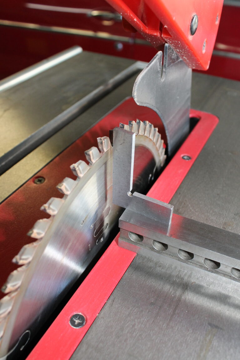
We need a range of squares to use for the many different situations we encounter in the workshop. For instance, we need a square to set up our machines – it is vital that your saw bench cuts square when you want it to. The blade obviously needs to be at right angles to the table and the sliding table or sledge needs to be square. The same for your planer.
The fence should be set square and you should regularly check that it remains square. Imagine the consequences of spending considerable time cutting mortise and tenon joints for fine furniture only to find they fit poorly due to the machined timber not being square. Errors also tend to compound over a project.